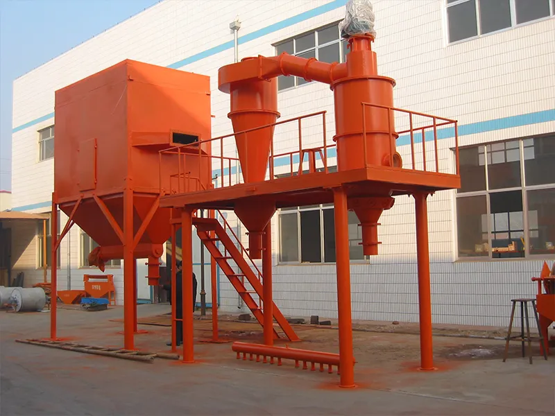
Most selection conversations begin with the machine type, so rotor shape, wheel count and housing layout are compared first. Nobody has checked whether the tonnage is achievable at the cut the buyer wants. The order is backwards. A capacity figure rests on three inputs, and two quotations cannot be compared until those inputs sit next to the number. A supplier who quotes 2 t/h without them is quoting another material.
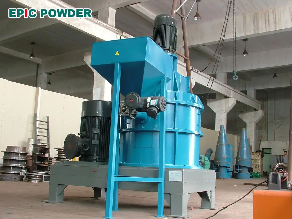
The Three Numbers Behind a Capacity Claim
The feed fraction, gamma, is the share of the incoming powder already below the cut size. A closed circuit mill usually delivers 50 to 75 percent. The grinding setpoint decides where in that band it lands. A change of setpoint or of deposit moves the figure, and the classifier has no influence on either.
The extraction rate, E, is the share of that fraction the rotor recovers into the fines. Bypass keeps it below 100 percent. Some fines fail to disperse and leave with the coarse stream, while others ride the rotor wake. Our model tables list this efficiency at 60 to 80 percent for the HTS machines and 60 to 90 percent for the ITC. A machine holding its conditions sits in the upper half of its band. Seal wear or an overloaded air system drops it toward the bottom. A sieve test on the coarse product finds that before any gauge does.
Extraction runs in two directions, and one letter covers both. Fines lost to the coarse stream set the tonnage, while coarse particles escaping into the product set the passing figure. The sharpness of the cut decides how the two trade, and it reads off the Tromp curve as kappa. Two machines with the same E can then differ twofold in coarse content.
The product requirement is the passing figure in the specification, stated as a mass fraction of product below the cut. It is a size criterion, so it does not trade against a chemical assay. A laser instrument returns a volume distribution, which stands in for mass only while the material holds a single density. A buyer who writes 97 percent below 10 µm returns every coarser particle to the mill, so each point added costs capacity.
Table 1. The quantities behind a capacity figure, and how each is measured
| Input | What it means | How to measure it | What moves it |
|---|---|---|---|
| Feed fraction below the cut | Share of incoming powder already fine enough | Laser or sieve analysis on the actual feed | Upstream mill setting, deposit, circuit load |
| Extraction rate E | Share of that fraction recovered in the fines | Mass balance across the machine | Rotor speed, air volume, feed concentration, seal condition |
| Cut sharpness kappa | How cleanly the rotor separates fine from coarse | Size analysis of both streams, plotted as a Tromp curve | Rotor geometry, wheel speed, residence time |
| Product requirement | Passing figure, as a mass fraction below the cut | Size test at the cut, with the dispersion pressure stated | Specification, and the sharpness of the cut |
Figures above describe common closed circuit practice on a carbonate feed. Every value has to come from the actual material.
Worked Example
Take a classifier fed at 2 t/h with ground calcium carbonate. Seventy percent of the feed is below 10 µm, and the extraction rate at that cut is 69 percent. One percent of the captured fines leaves with the filter dust. The product has to run 97 percent below 10 µm.
Target size in feed = Pa × gamma = 2 × 0.70 = 1.400 t/h
Captured by the rotor = 1.400 × 0.69 = 0.966 t/h
Target size in product = 0.966 × (1 – 0.01) = 0.956 t/h
P1 = 0.956 / 0.97 = 0.986 t/h
The coarse return takes everything that did not leave as product. The size balance is more reliable than subtracting P1 from the feed. The short form (1 – k)(Pa – P1) in most capacity sheets lands close and leaves a balance that does not close.
P2 = Pa × (1 – gamma) + Pa × gamma × (1 – E) – (P1 – target in product)
P2 = 0.600 + 0.434 – 0.030 = 1.004 t/h
The three streams close against the feed. Product, coarse return and filter dust come to 0.986, 1.004 and 0.010 t/h, for 2.000 t/h in total. Written against the feed, k gives 0.020 t/h of loss and a total of 2.010 t/h. That gap is what a buyer finds when the figures are checked line by line.
Two features of the result surprise buyers who read 2 t/h as a product figure. The product is under half the feed, and the circulating stream is larger than the stream that ships.
Change one input and the answer moves. At a feed fraction of 45 percent, the same machine and feed rate deliver about 0.63 t/h, since less finished material arrives with the feed.
Where the Capacity Goes
Bypass is the first loss and the easiest to miss. Fines leave with the coarse stream for two reasons. They enter the rotor zone too close to the blades, or the feed arrives too concentrated to disperse. A sieve test on the coarse product shows the symptom. More air or a lower feed rate recovers it at a cost in specific energy.
An over-tight specification is the second, and it is usually self-inflicted. A buyer who writes 99 percent passing where 97 serves the application returns more material to the mill. Specific energy rises and classifier capacity falls. The mill pays that cost, which is why it rarely shows in a comparison of quotations.
Feed concentration is the third. Past the air-to-solid ratio the machine loses dispersion, and an undispersed cluster behaves as one coarse particle. The cut then drifts coarse while rotor speed stands still.
The fourth sits downstream, where a filter that loads over a shift drops the air volume and the cut follows it. Pressure drop therefore belongs on the shift log next to rotor speed.
The fifth is the cut the buyer names, and it carries the next section.
Table 2. Where capacity goes, how it shows on the line, and what restores it
| Where capacity goes | What shows on the line | What restores it |
|---|---|---|
| Bypass of fines into the coarse stream | Fine material found in the coarse product | Raise air volume, reduce feed rate, check the rotor seal |
| Over-tight product specification | Growing return stream, rising specific energy | Agree the passing figure the application actually needs |
| Feed too concentrated | Cut drifts coarse at constant rotor speed | Raise the air-to-solid ratio, add a dispersing step |
| Filter pressure drop | Air volume falls over a shift | Clean or resize the filter, log the pressure drop |
| Very fine cut at high rotor speed | Throughput falls as the target D97 drops | Accept lower tonnage, or move to a larger machine |
What Happens When the Cut Gets Finer
D97 here means the size below which 97 percent of the volume lies. It is measured on a laser instrument in dry dispersion, with the pressure stated. The condition belongs to the figure, since 30 to 80 kPa of dispersion pressure moves D97 by 2 to 3 µm on the same powder.
Capacity and cut size are linked, and steeply. A machine holding 3 t/h at D97 45 µm will not hold it at 10 µm. The centrifugal field has to rise, and the air has to be pushed harder through the same rotor. Throughput falls to a half or a third across that range, and a guarantee without the cut compares a coarse number against a fine requirement.
Configuration Choices
Six configurations cover the range, and the D97 band narrows that list before capacity enters the discussion. A single wheel HTS classifier is the base case. A multi-rotor machine shares the air across several wheels and reaches a higher tonnage in the same diameter, at a higher investment. The ITC classifier opens a wider band for constrained layouts. The centrifugal CTC works the coarse end at high tonnage, and the MBS separator holds the middle band on volume duties. The turbo twin returns two products from one feed.
Table 3. Classifier configurations and the D97 range of each
| Configuration | D97 range | When it fits |
|---|---|---|
| Single wheel HTS | 3 to 150 µm | One grade at moderate tonnage |
| Multi-rotor HTS | 3 to 150 µm | High tonnage with a tight cut |
| ITC | 5 to 150 µm | A wide band, a constrained layout |
| MBS separator | 8 to 200 µm | Coarse to mid cuts at volume |
| CTC | 32 to 250 µm | The coarse end at high tonnage |
| TDC twin | 3 to 45 µm | A fine and a mid grade from one feed |
| Units in parallel | Set by the unit | Very large lines, each with its own air system |
Parallel units need their own air system and an intermediate silo, with standalone capacity slightly above the mill discharge feeding each one. A shared fan couples them, so a filter loading on one machine moves the cut on all of them.
How to Verify Capacity Before You Sign
Ask for a test on your own material, because the feed distribution and the extraction rate both come from the material. A full shift at the contract tonnage settles more than a specification sheet. The record carries feed rate, the three size distributions, rotor speed, air volume, filter drop and specific energy. A half-rate test flatters the cut.
Write the guarantee with its conditions: feed distribution, cut size, passing requirement and dispersion pressure. A guarantee missing those four cannot be tested and cannot be settled.
Five Items to Send
Five items decide the machine size, four from the customer and one from the supplier.
Table 4. The five items to send, and what each one decides
| Item | What it decides |
|---|---|
| Feed particle size distribution, with the test method | Feed fraction below the cut, and the mill setting behind it |
| Target cut and the passing figure required | Rotor speed, air volume and the return stream |
| Product tonnage, stated as finished powder | Machine size, and whether one unit is enough |
| Bulk density and flow behaviour of the feed | Dispersion step, air-to-solid ratio and feeder type |
| Grades per week and changeover tolerance | Whether a multi-rotor or a twin machine pays back |
Send them through the contact page, and the reply states a capacity at your cut with the assumptions visible.
About EPIC Powder Machinery. We build air classifiers and the circuits around them, from single wheel and multi-rotor machines to centrifugal and twin classifiers. Lab units for the trial before an order come from the same range. The HTS range covers the horizontal machines. Every project begins with a classification test on the customer’s material, reported with both curves and the extraction rate at the target cut. Write to mineral@epic-powder.com with the five items above.
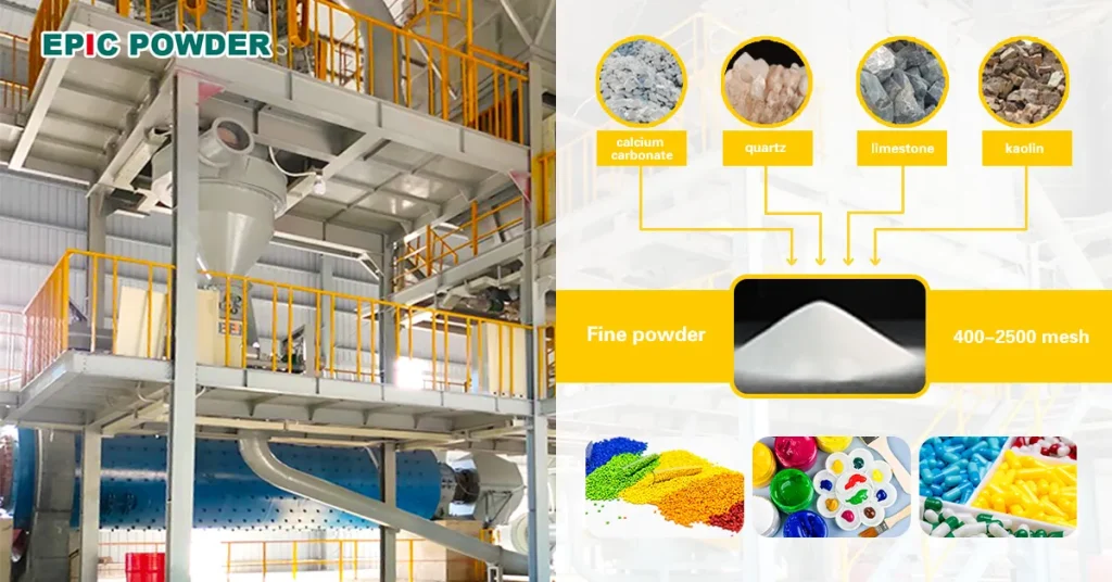
Epic Powder: Your Partner in Precision Powder Processing
Epic Powder designs grinding and classifying systems for minerals, chemicals, food, and pharmaceuticals. With more than 20 years of powder processing experience, we match the right mill to your target particle size and capacity. Tell us about your material and we will recommend a tested solution.

Thanks for reading. I hope my article helps. Please leave a comment down below.
You may also contact EPIC Powder online customer Molly representative for any further inquiries.
— Jason Wang, engineer