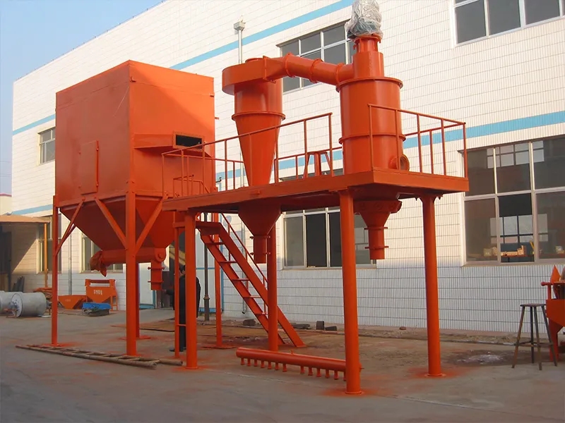
The classifier wheel is the critical component inside any air classifier. Its design, material, and performance directly determine your product’s particle size distribution, purity, and production efficiency. This guide covers everything from blade geometry and material selection to actual performance metrics. It can help you choose, operate, and maintain the right wheel for your powder processing production line.
1. What Is a Classifier Wheel and Why Is It the Core of the System?
1.1 Working Principle
Material enters the classification zone carried by the airflow. As the wheel rotates, particles are subjected to two opposing forces. Centrifugal force flings coarse, heavy particles outward; air drag pulls fine, light particles inward through the blade gaps toward the fine product outlet. The cut-off point is the particle size at which these two forces reach equilibrium.
1.2 Why Precision Is Critical
A sharp, stable cut-off point results in a narrow particle size distribution, less contamination from large particles, and higher product consistency. Even minor wear or poor design can broaden the particle size distribution, compromising downstream performance and batch acceptance rates. Precision is not a luxury but a production necessity.
2. Advanced Engineering Design: Factors Determining Classifier Wheel Performance
2.1 An In-Depth Look at Blade Geometry
Blade shape directly influences the flow field. Radially straight blades are simple but can cause turbulence. Angled blades help improve the rejection of larger particles. Curved blade profiles optimize air velocity distribution, giving sharper classification at higher throughput rates.
2.2 The Secret of Variable-Section Blades
Variable-section blades reduce radial velocity between blades while increasing tangential velocity at the rim. This produces a narrower particle size distribution and a finer cut point without simply increasing rotational speed.
2.3 Rotor Dynamics
Rim linear speed (m/s) is the primary design parameter determining the cutting particle size. Higher speeds result in greater centrifugal force, yielding finer products. EPIC Powder designs typically operate at rim speeds as high as 68 m/s to achieve sub-5-micron classification.
2.4 Sealing and Clearance Design
The clearance between the wheel and the housing serves as a leakage path for coarse particles. Labyrinth seals and air seals create a dynamic seal, forcing all material through the classification zone rather than bypassing it.
2.5 Feed Cones and Flow Channels
A well-designed feed cone distributes the material-air mixture uniformly across the classification wheel. Uneven feeding causes local overloads, shifts the local cut point, and ultimately broadens the overall distribution.
2.6 Single-Side vs. Double-Side Bearing Support
Single-sided support limits maximum rotational speed due to shaft deflection. Double-sided bearing support standard on the EPIC Powder TDC and HTS series. It enables higher rotational speeds with lower vibration, extends bearing life, and achieves clearer classification.
3. Classifier Wheel Materials
3.1 Stainless Steel (304/316L)
Good strength and corrosion resistance at a low cost. Best suited for general minerals with higher tolerance for metal contamination (50–120 ppm iron content). Heavy weight increases energy consumption.
3.2 Advanced Ceramics
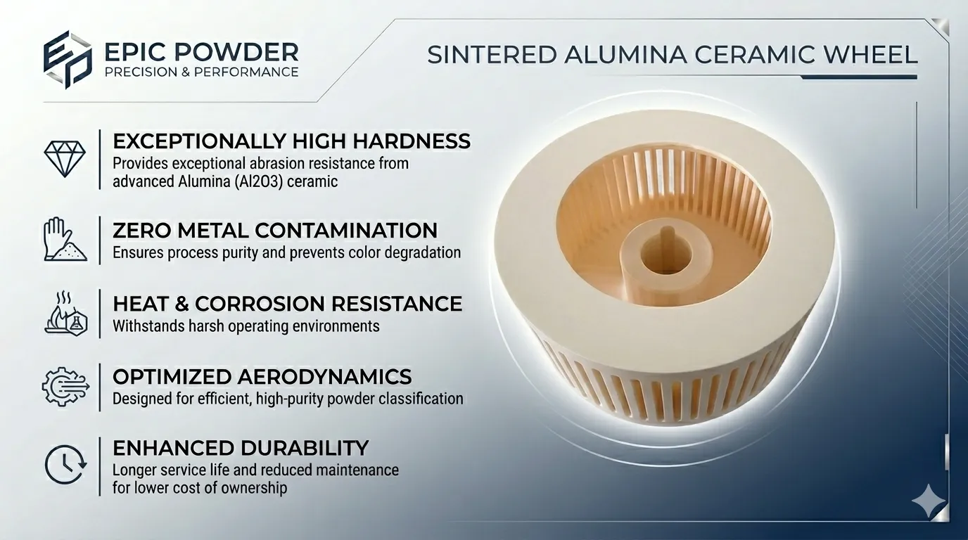
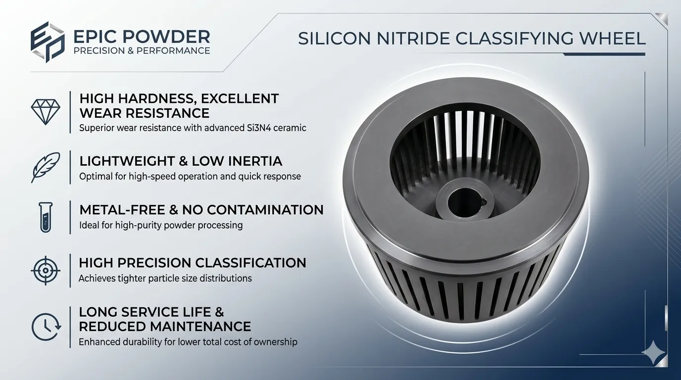
Ceramic wheels eliminate metal contamination, maintaining iron content below 10–20 ppm. Alumina offers high hardness at a moderate cost. Zirconia provides excellent fracture toughness. Silicon nitride withstands extremely high speeds and thermal shock. Silicon carbide resists the hardest abrasives. The trade-off is that ceramics are brittle, requiring upstream iron removal protection.
3.3 Tungsten Carbide
With a surface hardness of 85–92 HRA, its wear resistance is 3–5 times that of steel. Its high cost limits its use to applications involving the most abrasive materials, where frequent replacement of other wheels would be uneconomical.
3.4 Hardened Alumina
Low rotational inertia allows for rapid acceleration and high speeds with lower motor power. A hardened oxide layer (60–70 HRC) provides moderate wear protection. Ideal for low-abrasion, high-speed applications.
3.5 Material Selection Quick Reference Table
| Material | Wear Life | Contamination Risk | Cost | Best For |
| Stainless Steel | Moderate | Medium–High | Low | General minerals, non-abrasive powders |
| Alumina Ceramic | High | Very Low | Medium | Minerals, high-purity applications |
| Zirconia Ceramic | Very High | Near Zero | Medium–High | Battery materials, aggressive chemicals |
| Silicon Nitride | Very High | Near Zero | High | Ultra-fine grading, thermal cycling |
| Silicon Carbide | Extreme | Near Zero | High | Hardest abrasives |
| Tungsten Carbide | Extreme | Low | Very High | Maximum abrasion resistance |
| Hard-Anodized Al | Low–Moderate | Low | Low–Medium | High-speed, low-abrasion applications |
4. How to Measure and Evaluate the Performance of Classifier Wheels
4.1 Classifying Efficiency Curve
This curve depicts the percentage of particles of each size entering the coarse section. Perfect separation is represented by a vertical line at the cut-off point. The actual curve has a slope—the steeper the slope, the sharper the separation.
4.2 Cutting Sharpness Index (κ) and Top-Cut Control (D99/D97)
Cutting sharpness is typically quantified as κ = D25/D75 (for fine material) or D75/D25 (for coarse material). The closer the value is to 1, the sharper the separation. Strict D99 or D97 specifications require excellent top-cut control, which is directly related to blade design and sealing.
4.3 Throughput and Cut Size
Higher airflow increases throughput but also carries larger particles through, resulting in a coarser cut size. The optimal operating point involves balancing the target fineness with maximum throughput.
4.4 Energy Consumption
Lighter ceramic wheels consume less energy to rotate than steel wheels. Depending on the target fineness, material, and wheel design, typical energy consumption ranges from 15 to 50 kWh/ton.
4.5 Metal Contamination Rates
- Stainless steel wheels: 50–120 ppm iron contamination
- Alumina ceramic wheels: Less than 10–20 ppm iron
- Zirconia ceramic wheels: Near-zero metal ion leaching
For battery-grade NMC or LFP, this difference determines product compliance.
4.6 Wear Life Comparison
- Alloy steel wheels: 2,000–5,000 hours (moderate operating conditions)
- Alumina Ceramic: 40–60% longer lifespan than steel
- Zirconia Ceramic: Up to 10 times the lifespan of stainless steel
- Silicon Nitride: 3–5 times the lifespan of metal alternatives
5. System-Level Design Features for Maximized Performance
5.1 Variable Frequency Drive (VFD) Control, Real-Time Adjustment
VFD allows for online adjustment of the classifier wheel speed. Different products or target particle sizes require different centrifugal forces—VFD control enables this adjustment to be made instantly, without downtime.
5.2 Optimized Product Flow Paths to Prevent Recirculation
Poor housing design can cause already classified coarse material to re-enter the classifier wheel. EPIC Powder’s optimized flow paths direct fresh material directly into the classification zone, preventing recirculation and narrowing the particle size distribution.
5.3 Single-rotor and Multi-rotor Configurations
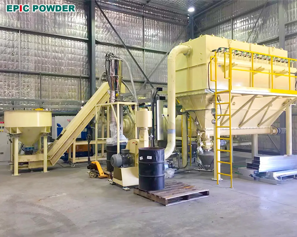
A single classifier wheel is suitable for lower production capacities. Multi-rotor classifiers (up to 4 or 6 wheels in a single housing) multiply throughput while maintaining a consistent cut point—EPIC Powder’s HTS series achieves capacities of up to 30 tons per hour at D97=3–45 μm.
6. Practical Tips for Operation and Optimization
6.1 Adjusting the Cut Point
– Increase rotor speed → finer product
– Increase airflow → coarser product, higher throughput
– Maintain a stable feed rate → stable cut point
Find the optimal balance through system testing, then lock in the parameters.
6.2 How Material Properties (Moisture, Density, Shape) Affect Performance
Moisture content exceeding 1% can cause agglomeration and blade adhesion. Higher particle density results in greater centrifugal force and a finer cut point. Irregularly shaped particles behave differently from spherical ones—be sure to calibrate using your actual material.
7. Maintenance Alert: Protecting the Design Integrity of the Classifier Wheel
7.1 Monitoring Wear Patterns and Blade Edge Condition
Inspect blade edges during every scheduled shutdown. Rounded, chipped, or worn edges reduce separation efficiency and broaden the particle size distribution. Track product fineness trends as an early indicator of wear.
7.2 The Importance of Precision Dynamic Balancing
At speeds of thousands of revolutions per minute, even slight imbalance can cause destructive vibrations. Always verify dynamic balance after cleaning, maintenance, or wheel replacement.
7.3 Preventing Material Accumulation: The Role of Surface Finish (Ra ≤ 0.2 μm)
Sticky or hygroscopic powders tend to adhere to rough surfaces. Specifying a mirror-polished finish on ceramic wheels minimizes material buildup, maintains clearance dimensions, and extends cleaning intervals.
7.4 Clear Indicators That a Classifier Wheel Needs Replacement
- Under standard settings, the product particle size distribution fails to meet specifications
- Visible edge wear, rounding, or chipping
- Increased vibration despite balancing
- Roughness or pitting on the blade surface
8. Engineering Practice
8.1 Norwegian Battery-Grade Lithium Iron Phosphate
An ITC classifier equipped with full ceramic protection and a high-precision classifier wheel with VFD control. Achieved D50 = 1.32 μm, D100 = 8.45 μm, with metal impurity levels meeting battery-grade standards.
8.2 Australian High-Purity Quartz
A ceramic-lined ball mill and an alumina classifier wheel system. Stable production of D50=7.5 μm product at a capacity of 1.5–2 tons/hour, achieving zero iron contamination and exceptional whiteness.
8.3 Thai Titanium Dioxide
HTS315-1 horizontal classifier equipped with a 315 mm classifier wheel. Achieves a stable D99 of 50–53 μm, with a 30% improvement in uniformity and a 50% increase in single-unit output to 2.5 t/h, while reducing energy consumption by 20%.
9. Frequently Asked Questions Regarding Classifier Wheel Design and Performance
Q: Can ceramic wheels achieve the same tip speed as metal wheels?
A: Yes. The rim linear speed of silicon nitride and zirconia classifier wheels typically exceeds 100 m/s, which equals or even surpasses the load-bearing capacity of metal wheels.
Q: How does the number of blades affect performance?
A: More blades result in greater centrifugal force and finer classification, but they reduce the open area and processing capacity. Fewer blades result in higher throughput, but a coarser cut point. The number of blades is a design compromise based on the target cut point.
Q: What is the main cause of a bimodal distribution in fine particles?
A: Coarse particles bypassing through gaps in the rim, or recirculation within the housing. First, check the seal clearance and internal flow channels.
Q: Can a single classification wheel be used for multiple products?
A: Yes, via VFD adjustment. However, cross-contamination must be considered; dedicated classification wheels are recommended for high-purity or abrasive products.
EPIC pOWDER
Selecting a classification wheel is not a standard off-the-shelf procurement decision. Blade geometry, material selection, bearing support, and seal design collectively determine the clarity of the classification step, contamination levels, and energy costs. At EPIC Powder Machinery, we design classifier wheels as part of a complete air classification system, covering a fineness range from D97 = 2 microns to 200 microns, with capacities ranging from pilot-scale to 30 tons per hour.
Need to specify the right classifier wheel for your process? Contact EPIC Powder today. Our technical team will provide the best recommendations for your customized equipment.

“Thanks for reading. I hope my article helps. Please leave a comment down below. You may also contact EPIC Powder online customer representative Zelda for any further inquiries.”
— Emily Chen, Engineer