The particle size distribution of cathode material is one of the most important variables in lithium-ion battery performance. Too wide a distribution and your electrode coating is uneven, ion diffusion is inconsistent, and capacity varies between cells. Too many oversized particles – even a handful of what engineers call killer particles – and you risk short circuits that end a battery’s life prematurely or, in the worst case, trigger thermal runaway.
Precision air classification is the processing step that controls this. It separates cathode powder into precisely defined size fractions using a controlled airflow and a dynamic classifier wheel, removing oversized particles, unwanted fines, and agglomerates without any chemical processing or contamination risk. It is dry, scalable, and tunable to a tight cut point.
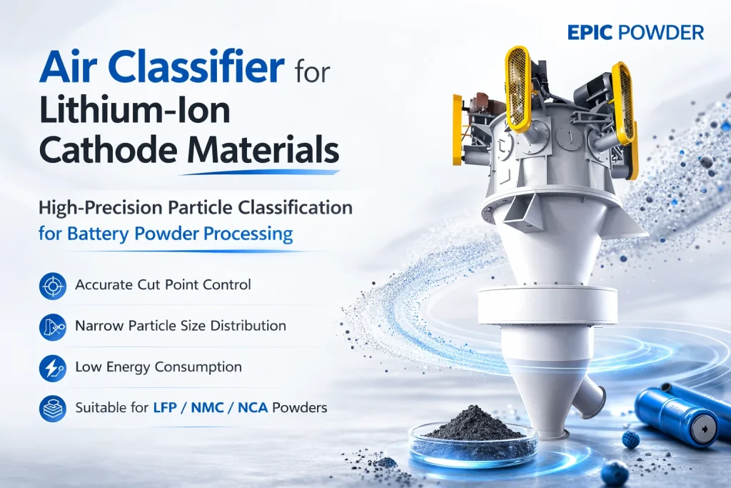
At EPIC Powder Machinery, we design and supply air classifiers for battery material production, with metal-free contact surfaces and classifier configurations optimised for NMC, LFP, LNMO, and other cathode chemistries. This article explains how air classification works, what it delivers at the battery level, and how to implement it correctly in your production process.
What Is Air Classification and How Does It Work?
An air classifier separates powder particles by size using the competing forces of centrifugal motion and aerodynamic drag. Inside the classifier, an airflow stream carries particles upward toward a spinning classifier wheel. The wheel applies centrifugal force to incoming particles:
•Fine particles: experience greater drag force relative to their mass and are carried through the classifier wheel with the airflow. They exit as the fine product fraction.
•Coarse particles: experience greater centrifugal force relative to drag and are thrown outward by the wheel. They fall back for further grinding or are collected as the coarse reject fraction.
The cut point – the particle size at which the classifier separates fine from coarse – is controlled by classifier wheel speed and airflow velocity. Increase wheel speed and the cut point moves finer. Decrease it and the cut point moves coarser. This is an adjustable, real-time parameter, not a fixed mechanical dimension like a screen mesh size.
Air Classification vs. Sieving vs. Jet Milling
| Feature | Sieving | Jet Milling | Air Classification |
| Primary function | Size separation only | Size reduction | Size separation only |
| Finest cut point | ~45 microns (325 mesh) | D50 to 1 micron | D50 to 1-2 microns |
| Changes particle chemistry? | No | Can (surface damage at high energy) | No |
| Metal contamination risk | Low (wire mesh) | Low-medium (nozzle wear) | Near zero (metal-free design) |
| Cut point adjustability | Fixed (screen change needed) | Via classifier wheel speed | Via classifier wheel speed |
| Suitable for <20 micron cut? | No | Yes (with classifier) | Yes |
| Throughput scalability | Limited at fine sizes | High | High |
Why Particle Size Distribution Determines Battery Performance
Cathode material particle size affects battery performance through four direct mechanisms. Understanding these helps you set the right classification specification for your application.
1. Electrode Packing Density
Cathode particles must pack together tightly in the electrode to maximise the amount of active material per unit volume – this directly determines volumetric energy density. A narrow, controlled PSD allows better packing than a broad distribution. Some manufacturers target a bimodal distribution (two size populations) where small particles fill the voids between large ones, further increasing packing density. Air classification is the tool that creates both the narrow distribution and, when combined with a second grinding stage, the precise small-particle fraction for bimodal blending.
2. Lithium-Ion Diffusion Kinetics
Lithium ions must diffuse through the solid cathode particle during charging and discharging. The diffusion time scales with the square of the particle radius – halving the particle size reduces diffusion time by four times. This means finer, more uniform cathode particles deliver better rate capability and faster charging. But going too fine increases surface area, accelerates side reactions with the electrolyte, and reduces cycle life. The right particle size is a balance – and air classification is how you hit and hold that balance consistently.
3. Electrode Coating Uniformity
Cathode slurry is coated onto the current collector foil as a continuous film. If the particle size distribution is broad – with a mix of coarse and fine particles – the slurry rheology is inconsistent and the resulting coating has uneven thickness and density. This translates directly to variable capacity across the electrode area, which means variable capacity across cells and packs. A narrow PSD produces more consistent slurry behaviour and more uniform coating.
4. The Killer Particle Problem
Oversized particles in cathode powder are known in the battery industry as killer particles. A single particle significantly larger than the electrode coating thickness can penetrate through the separator during calendering or cycling, creating a direct short circuit between cathode and anode. The consequences range from accelerated self-discharge to thermal runaway.
Killer particles are typically defined as any particle above 2-3 times the nominal D99 of the specification – often in the 30-80 micron range for fine cathode grades. Conventional sieving cannot reliably remove them at these sizes and throughputs. Air classification with a precisely set upper cut point is the reliable industrial solution.
| Cathode PSD Specifications by Chemistry (Typical Targets) NMC 622 / 811: D50 8-15 microns | D99 <40 microns | No particles above 50 microns LFP (standard): D50 1-5 microns | D99 <20 microns | No particles above 30 microns LFP (high energy density): D50 3-8 microns | D99 <25 microns | Bimodal distribution for packing LNMO (high voltage): D50 5-12 microns | D99 <35 microns | Tight span critical for voltage stability Note: Specifications vary by electrode design and application. Confirm with your cell design team. |
How to Implement Air Classification in Cathode Material Production
Step 1: Characterise Your Feed Material
Before selecting or configuring a classifier, measure your feed material’s particle size distribution, bulk density, and flow characteristics. This tells you three things: where your current PSD sits relative to your target, how much oversize material you are generating upstream, and what airflow parameters the classifier will need to handle your specific powder density and flowability.
For NMC and other layered oxide cathodes, also check for agglomerates – particles that have sintered together at their surfaces during calcination. Agglomerates measure as large particles in laser diffraction but break apart under classification airflow, which affects your effective feed PSD. A de-agglomeration step before classification, or an in-classifier de-agglomeration design, may be needed.
Step 2: Select the Right Classifier Type
Two classifier architectures are most commonly used for battery cathode materials:
- Dynamic (turbine) air classifier: the classifier wheel spins at high speed, creating a sharp centrifugal cut. Highly adjustable cut point (D50 to 1-2 microns achievable), suitable for fine NMC and LFP grades, and available in metal-free designs for battery applications. This is the standard choice for cathode material classification.
- Multi-rotor air classifier: uses multiple classifier wheels in series, which produces a sharper separation than a single-rotor design at equivalent throughput. Best suited for high-volume production where the tightest possible PSD control at rates above 500 kg/h is the priority.
For both types, specify metal-free contact surfaces (ceramic, polymer, or stainless steel linings) for cathode material applications. Iron and chromium contamination from steel surfaces at even single-digit ppm levels can affect electrode performance and cycle life.
Step 3: Optimise the Cut Point
Set the classifier wheel speed and airflow to achieve your target D50 and D99. This typically requires 3-5 trial runs with sampling and laser diffraction analysis at each setting. The key parameters to vary:
•Classifier wheel speed: primary control for cut point. Higher speed moves the cut finer.
•Airflow velocity: affects the drag force on particles. Higher airflow moves the cut coarser for a given wheel speed.
•Feed rate: higher feed rates increase particle concentration in the classification zone, which can slightly coarsen the cut due to particle-particle interactions. Establish the optimal feed rate and hold it constant.
Once the optimal parameter set is established, document it as your process recipe for this material and target PSD. Classifier performance is highly reproducible once the recipe is set.
Step 4: In-Line Monitoring and Quality Control
For production-scale operations, in-line particle size monitoring at the classifier product outlet allows real-time detection of PSD drift before it reaches the electrode coating line. Laser diffraction sensors designed for continuous dry powder measurement are available and integrable with classifier control systems for automatic feedback adjustment.
At minimum, sample and measure product PSD at the start of each production batch and after any feed material change. The classifier cut point is stable once set, but changes in feed particle size from upstream grinding affect the output PSD.
Real Production Results: Before and After Air Classification
CASE STUDY
| NMC 622 Producer Reduces Rejects and Improves Electrode Yield by 15 The problem A lithium-ion battery materials manufacturer producing NMC 622 cathode powder was seeing inconsistent electrode coating density and variable electrochemical performance across batches. Laser diffraction analysis of their cathode powder revealed a broad PSD with D99 regularly exceeding 55 microns – well above their electrode design specification of D99 below 40 microns. The solution EPIC Powder Machinery supplied a dynamic air classifier with a metal-free classifier wheel, configured to hold D50 at 12 microns and D99 below 38 microns. The classifier was installed after the existing calcination and milling steps, acting as a final quality gate before the powder entered slurry preparation. Results PSD: D99 consistently below 38 microns across all production batches Slurry rheology: coating viscosity variance reduced by 40%, enabling tighter coating weight control Production yield: defective electrode batch rate dropped from 12% to below 2%, giving a net 15% increase in usable yield Energy density: improved by 3-4% due to better electrode packing from the tighter PSD |
What to Look for in an Air Classifier for Cathode Materials
Not all air classifiers are suitable for battery cathode applications. The requirements are more demanding than typical industrial powder classification. Here is what matters:
•Metal-free contact surfaces: any metal wear debris reaching the cathode powder contaminates it. Specify ceramic, polymer-lined, or high-grade stainless steel construction for all surfaces that contact the product. EPIC Powder Machinery’s battery material classifiers use metal-free classifier wheels and linings throughout the product contact path.
•Sharp cut point (high selectivity): the separation efficiency index (also called the sharpness of cut, k = d25/d75) should be above 0.6 for battery cathode applications. A classifier with poor selectivity produces a broad overlap between the fine and coarse fractions, which defeats the purpose of classification.
•Stable, repeatable performance: the cut point must be stable across long production runs and batch-to-batch. Look for classifiers with PID-controlled wheel speed drives and stable airflow regulation rather than simple fixed-speed designs.
•Scalability: the same classifier design should be available at lab scale (1-10 kg/h for R&D) and production scale (100-2000 kg/h for manufacturing). Scaling up a different classifier design often changes the cut point and selectivity – stay with the same design geometry at different sizes.
•Closed-loop integration: the classifier should integrate cleanly with your upstream milling step so that coarse rejects can be returned for regrinding rather than discarded. This maximises material yield and minimises waste in an expensive cathode material.
Discuss Your Cathode Material Classification Requirements
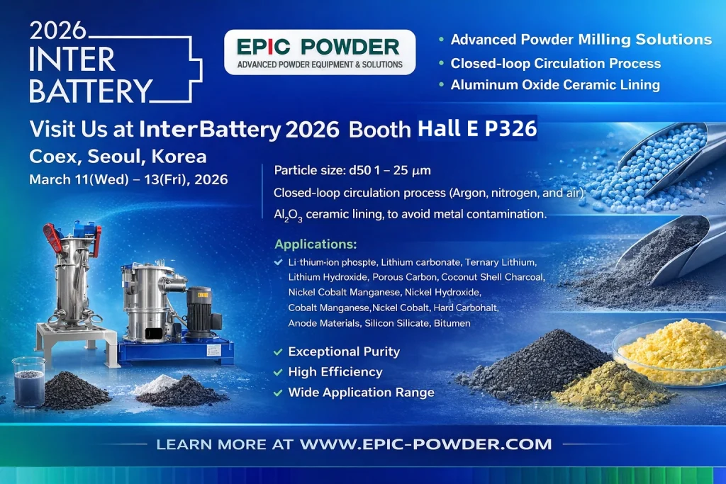
| Whether you are classifying NMC, LFP, LNMO, or another cathode chemistry, EPIC Powder Machinery’s air classifiers are configured for battery material purity and precision. Metal-free contact surfaces, dynamic classifier wheels with tight cut-point control, and scalable systems from lab to production — all available with free material trials before you commit.Send us your feed material data and target PSD and we will recommend the right classifier configuration and run a trial grind. Request a Free Material Trial: www.powder-air-classifier.com/contact Explore Our Battery Material Air Classifiers: www.powder-air-classifier.com |
Frequently Asked Questions
What is the typical particle size range for cathode materials after air classification?
It depends on the cathode chemistry and cell design. For NMC cathodes (NMC 622, NMC 811), typical classification targets are D50 8-15 microns with D99 below 35-45 microns. For LFP, targets are finer: D50 1-5 microns for standard grades and D50 3-8 microns for high energy density grades, with D99 typically below 20-25 microns. The critical number is often D99 or the maximum particle size – the killer particle specification – rather than D50 alone. Air classification can consistently hold D99 below any specified upper limit from about 5 microns upward, which sieving cannot do reliably at cathode material production throughputs.
What are killer particles and why do they matter so much?
Killer particles are oversized particles in cathode or anode powder that are significantly larger than the electrode thickness. During electrode calendering (compression), these particles can punch through the thin polymer separator that separates cathode from anode inside the cell. The result is a micro short circuit. Depending on severity, this causes accelerated self-discharge, rapid capacity fade, or in the worst case, thermal runaway and cell failure. The insidious aspect of killer particles is their low frequency – they may represent less than 0.01% of the total particle count, making them nearly invisible to standard particle size testing. Air classification removes them reliably by setting an upper cut point that no particle can exceed in the product stream.
How is air classification different from jet milling for battery materials?
Jet milling and air classification perform different functions, though they are often used together. Jet milling reduces particle size – it fractures particles through high-velocity particle-on-particle collisions. It does change particle size and can affect surface chemistry. Air classification only separates particles by size – it does not fracture them and does not change particle chemistry. For cathode materials, jet milling (or other milling) produces the target size range, while air classification ensures a tight, consistent PSD and removes oversize particles. The best cathode powder processing lines typically combine upstream milling with downstream air classification. The mill does the size reduction work, the classifier ensures the final product meets spec every batch.
Can air classification remove magnetic impurities from cathode powder?
No. Air classification separates particles by aerodynamic properties – size, shape, and density. It does not respond to magnetic properties and cannot remove paramagnetic or ferromagnetic contamination. For magnetic impurity removal, a high-gradient magnetic separator (HGMS) is needed, typically rated at 10,000-15,000 Gauss for battery material applications. In a complete cathode material processing line, magnetic separation and air classification are complementary steps – often both are needed. The magnetic separator removes metallic contamination; the air classifier controls particle size distribution and removes killer particles.
How do you clean an air classifier between different cathode material batches?
Cross-batch contamination is a real concern, particularly when switching between different cathode chemistries (e.g., NMC to LFP) or between production and R&D grades. The standard cleaning protocol is: (1) run the classifier empty with clean dry air for 5-10 minutes to purge residual powder from the circuit; (2) disassemble the classifier wheel housing and product collection vessel and wipe down with a clean, lint-free cloth or brush; (3) use compressed air to clean any dead zones in the feed inlet and reject outlet paths; (4) reassemble and run a sacrifice batch of the new material, collecting it separately, before starting the production batch. For high-value NMC materials, a full wet wipe-down with isopropanol followed by a dry purge is recommended before switching chemistries.
Epic Powder
Epic Powder, 20+ years of work experience in the ultrafine powder industry. Actively promote the future development of ultra-fine powder, focusing on crushing, grinding, classifying and modification process of ultra-fine powder. Contact us for a free consultation and customized solutions! Our expert team is dedicated to providing high-quality products and services to maximize the value of your powder processing. Epic Powder—Your Trusted Powder Processing Expert!

“Thanks for reading. I hope my article helps. Please leave a comment down below. You may also contact EPIC Powder online customer representative Zelda for any further inquiries.”
— Jason Wang, Engineer